
Part Number: CC22102
CFE18 stands for "Can Bus Function Extension" or colloquially also "Can Switch Board" - why is this module needed?
Can bus connections in the vehicle sometimes present our customers with great challenges. Especially in motor sports applications, when electronics have to be accommodated in the steering wheel and information from adjustment knobs (trimpots) or pushbuttons is then to be transmitted via Can Bus.
CANchecked now offers a small add-on module that has 18 connections: 9 for pushbuttons and 9 for analog inputs (0-5V signal). A voltage converter to ensure connection to a 12V vehicle electrical system is also already integrated.
")
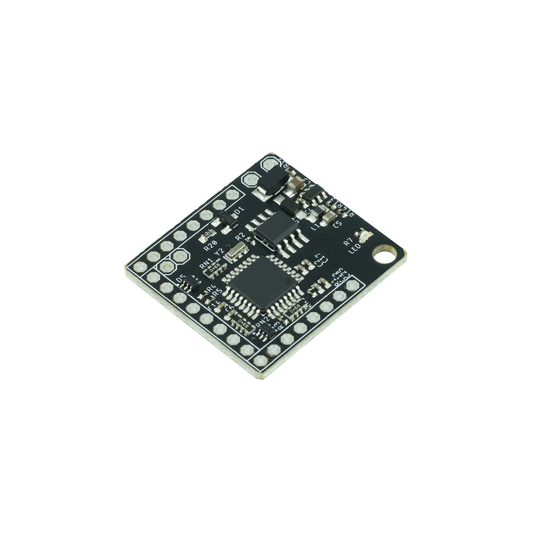
- The CFE18 hardware -
With only 29x27mm, the circuit board is very compact and can be placed anywhere. The pin pitch is 2.54mm - 3.81mm for the power supply for safety reasons.
We have made a hole for attachment, which can be used as a screw connection.

CFE18 - Can Bus Termination
A solder jumper is attached to the circuit board.
If you close this, the Can Bus termination with 120 ohms is active. By default the solder jumper is OPEN .
- Connections -
| 12V / GND (top) | Power supply 6-22V (protected against polarity reversal) |
| A0-A8 | 9 analog inputs (0-5V) |
| D0-D8* |
9 digital inputs (maximum 5V) (internal pullup 20-50K) *D8 omitted with v0.8 |
| 5V/SGND | Power supply for analog sensors or sensor ground |
| CANL/CANH |
Can Bus connection (Can Low, Can High) CAN 2.0 A/B – 125, 250, 500, 1000 kbps |
| AUX1-3* | Low side outputs 0.5A maximum - *from board v0.8 |
| RX/TX/DTR/GND |
optional: for possible updates (additional hardware required) |

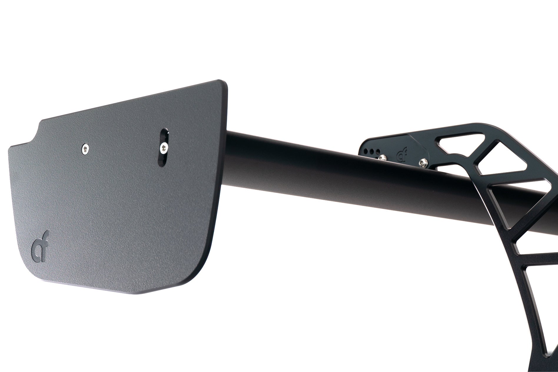
- Motorsport steering wheel -

One application would be a motorsport steering wheel. In the picture you can see the approximate size, the steering wheel hub is 50mm in diameter. With only 4 connections via a spiral cable, a wide range of inputs can be transmitted via CAN bus.
Thanks to PT Motorsport Electronics for the excellent example image of how the integration of our Can Switch Board can be done.
- connection options -

Switches (switches) as well as trimpots (adjustment knobs) can be connected to the CFE18.
But sensors such as oil pressure, fuel pressure, boost pressure, exhaust back pressure and integration into a separate housing would also be conceivable.
- CFE18 connection / Default Can Bus Stream -
The input data is queried and transmitted every 50ms (100Hz - variable from 1Hz to approx. 300Hz - depending on the smoothing ). The data is transmitted as "unsigned big endian".
As soon as 12V and ground are connected, the green status LED on the front lights up and the Can Bus data is transmitted.
Can Bus ID: 0x700 ( Base Data CAN ID – changeable)
| byte | 0 | 1 | 2 | 3 | 4 | 5 | 6 | 7 |
| BaseID | AIN0 0-1023 | AIN1 0-1023 | AIN2 0-1023 | AIN3 0-1023 | ||||
| Base ID +1 | AIN4 0-1023 | AIN5 0-1023 | AIN6 0-1023 | AIN7 0-1023 | ||||
| Base ID +2 | AIN8 0-1023 | bit masked DIN0-7 | DIN0 0-1 | DIN1 0-1 | DIN2 0-1 | DIN3 0-1 | DIN4 0-1 | |
| Base ID +3 | DIN5 0-1 | DIN6 0-1 | DIN7 0-1 | DIN8 0-1 | unused | *version | ||
*from software version 3
- Digital outputs -
*From hardware v0.8
From hardware 0.8, the CFE18 has three digital outputs. These can be loaded up to a maximum of 500mA and switch to ground (LOW SIDE).
To do this, a Can Bus frame is sent every 100ms (CAN Id can be configured here - from a 500ms pause between the frames, the timeout is activated and the outputs are deactivated): (
0=inactive, 1=active)
| byte | 0 | 1 | 2 | 3 | 4 | 5 | 6 | 7 |
| CAN RX ID (default: 0x640) |
AUX1 0/1 |
AUX2 0/1 |
AUX3 0/1 |
unused | ||||
The setting is made via Can Bus - see configuration options
- AIN smoothing -
*From software version 3
If the analog inputs fluctuate too much, they can be smoothed out using software. This can be configured separately for each analog input.
The analog inputs are evaluated with each transmission (default: 20Hz).
| Attitude | smoothing |
| 0 | no smoothing |
| 1 | 2 |
| 2 | 4 |
| 3 | 8th |
| 4 | 16 |
| 5 | 32 |
| 6 | 64 |
For example, if a smoothing factor of 4 is set, the average of the last 16 measurements is taken. This makes the value calmer (smoother), but also reacts with a delay to fluctuations. You have to find a healthy middle ground here.
The setting is made via Can Bus - see " Configuration options "
- configuration options -
The following values can be adjusted via Can Bus:
| Data CAN ID: | with which Can Id the data is sent | default: 0x700 |
| Configuration CAN ID: | with which CAN Id the board can be configured - RESTART required | default: 0x70A |
| Frequency: | with which the data is sent via the CAN bus in milliseconds | Default: 10ms = 100Hz |
| Can Bus Speed: | 1=125kbps, 2=250kbps,3=500kbps,4=1Mbit - RESTART required | Default: 3 = 500kbps |
| Mode: | 0=default, 1=EMUv3, 2=Haltech IO12B, 3=Haltech IO12A+B, 4=Motec | Default: 0 |
| *Smoothing: | smoothing of the analog inputs, configurable for each input (0-6) | Default: 1 |
*from software version 3
Byte 0+1 are always 0x0C and 0x0A
Byte 2 feature starting with 0x0A
Features:
can id: 0x0A (high byte) + 0x0B (low byte)
config can id: 0x0C (high byte) + 0x0D (low byte)
frequency: 0x0E
can bus speed: 0x0F
mode: 0x10
can id RX: 0x12 (high byte ) + 0x13 (low byte) from CFE18 v0.8
Example 1: change data can id to 0x600
| can id | bytes 0 | bytes 1 | byte 2 | byte 3 | byte 4 | byte 5 | byte 6 | byte 7 |
| 0x70A | 0x0C | 0x0A | 0x0A | 0x06 | unused | |||
| 0x70A | 0x0C | 0x0A | 0x0B | 0x00 | unused | |||
Example 2: change frequency to 50Hz (20ms = 0x14 in hex)
| can id | bytes 0 | bytes 1 | byte 2 | byte 3 | byte 4 | byte 5 | byte 6 | byte 7 |
| 0x70A | 0x0C | 0x0A | 0x0E | 0x14 | unused | |||
Example 3: change can bus speed to 1Mbit
| can id | bytes 0 | bytes 1 | byte 2 | byte 3 | byte 4 | byte 5 | byte 6 | byte 7 |
| 0x70A | 0x0C | 0x0A | 0x0F | 0x04 | unused | |||
Example 4: change mode to EMUv3
| can id | bytes 0 | bytes 1 | byte 2 | byte 3 | byte 4 | byte 5 | byte 6 | byte 7 |
| 0x70A | 0x0C | 0x0A | 0x10 | 0x01 | unused | |||
Example 5: change smoothing on AIN1 to 4 (=16)
| can id | bytes 0 | bytes 1 | byte 2 | byte 3 | byte 4 | byte 5 | byte 6 | byte 7 |
| 0x70A | 0x0C | 0x0A | 0x14 | 0x04 | unused | |||
(0x14 = AIN1, 0x15 = AIN2, 0x16 = AIN3, 0x17 = AIN4, 0x18 = AIN5, 0x19 = AIN6, 0x1A = AIN7, 0x2B=AIN8)
- Control unit / ECU configuration -
The analog inputs provide a 10-bit resolution and therefore values from 0 to 1023. The value must be converted in the control unit. All values are "unsigned big endian"
Examples:
5V voltage AIN0
0x700 Byte0+1
Multiplier: 5; divisor: 1023; Offset: 0
or multiplier: 0.004887585533
Exhaust gas temperature (type k) AIN7:
0x702 Byte6+7
Multiplier: 1250; divisor: 1023; Offset: 0
or multiplier: 1.2218963832
Either the individual bytes are used for the digital inputs. Eg DIN6: 0x702 byte 6 or the bit mask at 0x702 byte2
eg DIN6: 0x702 Byte2 Mask:0x40
 Analog input 4 with a type K converter
 Digital input 6
- Documentation / Downloads -
You can also download this page as a PDF here: